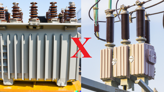
Is there a point of equilibrium in the relationship between Power and Voltage for transformer design? There are no records in the literature (not identified by me, at least) that this relationship is fully defined, but when the transformer has characteristics that differ greatly between its voltage level and operating power, some technical challenges are generated that must be fully overcome during the calculation and design phase to guarantee full operation of this equipment in the field.
The challenges of designing low-voltage, high-power transformers were already addressed, and now, in this article, the technical challenges of designing low-power transformers for high-voltage systems will be discussed. The characteristics discussed in this article can be applied broadly, but for reference purposes, transformers with a voltage class ≥138 kV and three-phase power up to ≤15 MVA (or respectively single-phase power up to ≤5 MVA) can be considered.
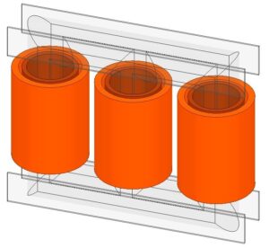
Construction characteristics of the windings and the distribution of capacitances.
In general, the most critical points in the design of these low-power transformers, which will be subjected to high voltage levels, are mainly related to the dielectric dimensioning of the winding insulation. The reduced dimensions of the wires and also of the windings themselves (reduced size due to the low power), define very specific values for the internal capacitances, which are used in the models generated for calculating the distribution of internal dielectric stresses.
In general, a tendency towards a decrease in series capacitance and a non-directly proportional change in the value of parallel capacitance is observed, altering the alpha factor (𝛼) which is used to calculate the voltage distribution in the winding (damping factor of the voltage signal along the winding). This unsynchronized change in series capacitance relative to parallel capacitance can cause an atypical voltage distribution inside the winding which, if this condition is not foreseen in the design, can compromise the insulation, especially in the region of the turns at the winding input.
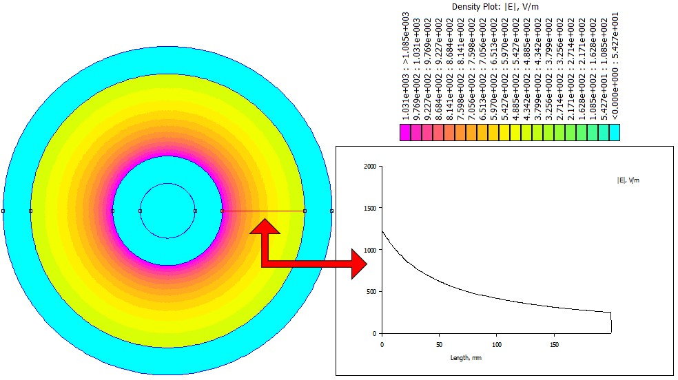
Distribution of the electric field in the windings
The windings of a transformer with a high voltage level and low power will exhibit a concentration of electric field at the ends of the coils for two main reasons:
- The first reason is that the radial dimension of these windings is relatively smaller and, as already well defined in the literature, the electric field has a higher amplitude in potentiated elements with geometric characteristics endowed with small radii. This condition, which generates a significantly reduced radial dimension of the windings, makes it difficult to insert elements to equalize the electric field at the ends, such as equipotential rings and insulating elements for over-insulation of these critical points (sheaths and other molded insulating materials).
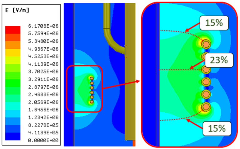
- The second reason is related to the large difference in diameters between the low and high voltage windings. Since this configuration generates a high dielectric strength at the winding ends (due to thickness versus distance between them), the insulation channel between the low and high voltage windings is relatively large, thus altering the electric field distribution and increasing the dielectric requirement closer to the winding with the smaller diameter. To visualize this phenomenon, a finite element software was used to perform a numerical simulation of a simplified model of two concentric windings with significantly different diameters, shown in the following figure. The results in the following figure show that the electric field is not constant in the insulation channel between windings and exhibits a non-linear decay with a much higher value near the winding with the smaller diameter (for windings of similar diameters, the electric field in the insulation channel between them has a more stable characteristic and lower amplitude).
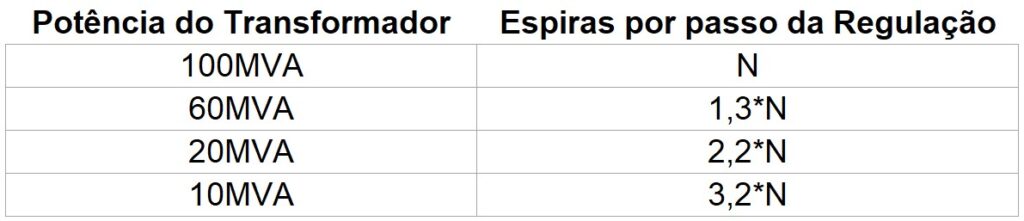
Projeto do enrolamento de regulação
In the design of lower power transformers, relatively more turns are used to achieve a balanced design for the same voltage level. Therefore, the regulating windings, which are normally designed for adjustments of up to 10% in 1.25% steps, must be designed considering this higher number of turns. To illustrate, maintaining the same voltage level of a transformer (for example, 138/13.8kV) and decreasing its power, the number of turns in each regulation step changes approximately as shown in the following table:
Characteristics of the winding connection elements
Low-power, high-voltage transformers have very low current levels, and therefore, if only the current is considered when sizing the cables and connecting elements of the active part, a very high electric field may arise, even greater than the dielectric withstand capability of the insulating fluid, creating conditions for dielectric breakdown (electrical discharge). Thus, in these cases, it is necessary to size the conductor diameter and its respective insulation considering the voltage level that will be imposed on these points of the transformer during equipment release tests or after operation.
Distribuição do campo elétrico em elementos de ligação da parte ativa.
Fonte: Dissertação de Odirlan Iaronka disponível Neste Link.
Final considerations
The objective of this article was to describe some design points that should be observed when designing low-power transformers subjected to the dielectric requirements of high-voltage systems. In general, the most critical points are related to the dielectric insulation of these transformers, which must be evaluated and resized to a higher level according to the results obtained during the initial design and calculation phase. For this evaluation, for example, analytical formulations can be used when dealing with known geometries, or finite element simulation tools and numerical tools when dealing with complex geometries or those lacking characteristics that allow for the application of studies with planar or axisymmetric symmetry.
Now, a comment is in order regarding the manufacturing/acquisition cost of these special transformers discussed in the previous articles (Low voltage and high power transformer – discussed in the previous article and High voltage and low power transformer – discussed here): both situations increase the price of the asset due to the amount of raw material needed, which is added to the electrical, magnetic, thermal and mechanical design to guarantee the same safety margin of equipment with a balanced relationship for the Power X Voltage parameters.