For many years, transformers for rectifiers/inverters failed due to premature aging caused by excessive heating. Over time, and with the development of various standards (IEEE C57.110 and IEC 61378 are good examples), the effect of harmonic current components became better understood and properly associated with overheating in transformer windings.
The following figure helps us understand the power flow in these systems. It’s important to note that the power system imposes the voltage, and the inverter and load define the current waveform.

Today we all know that current harmonics cause frequency-dependent transformer losses to increase. These losses are parasitic losses in the windings or in beams, tanks, and other metallic elements, due to the stray field. To make matters worse, parasitic losses are generally more intense at the ends of the windings, and their increase directly affects the hottest point of the transformer (the hot spot). This was the cause of so many transformer failures, since the hot spot temperature is the factor that most influences the lifespan of this equipment. It is often said that for every 6 °C increase in the hot spot, the lifespan of the transformer is halved (in fact, this is a fact and a consequence of applying the Arrhenius equation, which IEC 60076-7 explains adequately).
The aforementioned standards ended up defining some quantities that help us to more easily define the impact of current harmonics on transformers. The ‘K-factor’ and ‘FHL’ are some ways of expressing the increase in parasitic losses in the transformer. In rectifier applications, K-factor values between 4 and 8 were common, and could reach 13 or more for some more extreme applications where filters were not applied.
It’s worth remembering that multipulse transformer configurations, such as 12, 18, and 36, help reduce the components transmitted to the grid (they are actually drained from the grid). Regarding the order of harmonic components in these transformers for rectifiers, the most significant were the 5th and 7th, followed by the 11th and 13th, and so on, always in the pattern N*6±1, where N is a natural number. However, the higher the order of the harmonic, the smaller its amplitude. Who doesn’t remember the nomograms from Professor Ivo Barbi’s book?
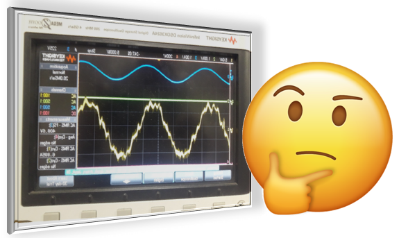
There is another relevant factor in this context, which is the voltage and current distortion rate, THDv and THDi. In the case of transformers for rectifiers, THDi values greater than 15% are not uncommon.
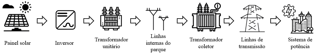
Now let’s see what happens in a photovoltaic power generation park, the solar parks. As the following figure indicates, we now have a different flow. It is no longer so clear who imposes the current or voltage, but the fact is that the collector transformer current is the sum of the current of all the unit transformers. And these parks need to meet a very specific power quality condition: THDi less than 5%.
This indicates that the current harmonics generated by photovoltaic generators are lower than those in the rectifier systems discussed in the introduction. And that is exactly what happens. The power quality requirement is one of the reasons for this, but there are other important points. One of them is the order of the harmonics; unlike rectifiers, the harmonics in photovoltaic generators depend on the switching frequency of the semiconductors (currently silicon-carbide is the most common), which can reach up to 4 kHz. The main harmonics will be multiples of the switching frequency; therefore, in a 60 Hz system, they will start near order 66 and will be relevant again at order 132. The positive point is that the higher the harmonic order, the easier it is to filter, and photovoltaic systems undoubtedly do this (as mentioned here).
Ultimately, it’s unlikely that the transformer will ever be subjected to a K-factor greater than 3. This isn’t irrelevant, but it’s a significant change from previous applications involving power electronics, and we need to think twice before attributing any excess heating to current harmonics. And another interesting point: using multipulse transformers doesn’t help at all, since low-order harmonics aren’t present.
The objective of this article is more expository, aiming to make us think a little more about these applications, which are trending not only in Brazil.