The evolution of the global energy matrix brings to light technical challenges that require a readjustment of design strategies. In this article, we will discuss reverse flow in transformers and its impact on the thermal design and insulation of the equipment, as well as some strategies to identify and mitigate the effects of this phenomenon.
In general, from the point of view of equipment operation, the occurrence of a reverse flux can cause a distortion in the equipment current (harmonics), altering the distribution profile and the amplitude of losses in the equipment. This phenomenon can be even more significant for multi-winding transformers or those equipped with regulating windings (no-load or on-load tap changer).
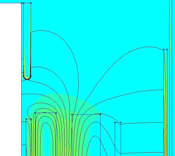
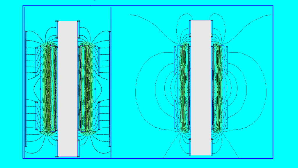
This change occurs both in the losses in the windings themselves and in the losses in the metal fastening parts of the active part or the tank. This happens because the reverse flux alters the characteristics of the winding current and, consequently, also modifies the distribution of the machine’s stray magnetic field, causing parasitic losses.
In practice, what can happen is an increase in the operating temperature of the equipment, mainly in the temperature of the top of the oil and in the temperature of the hottest point of the winding (hotspot).
So the question arises: is it possible to monitor or verify this condition in transformers in operation?
From the point of view of changes in the total loss value, it is relatively simple to diagnose any alteration, mainly because it will alter the temperature rise of the top of the oil. As this parameter is normally measured continuously and directly on the equipment in operation, when predefined values are reached, the corresponding alarms and protections can be triggered.
However, when it comes to altering the temperature rise distribution of the hottest point in the winding or internal metal parts, a hidden danger can arise. This is because, unfortunately, these points are more difficult to monitor, especially in older transformers that were manufactured without direct temperature measurement systems for the winding or hardware (currently done using fiber optic sensors).
It’s worth noting that some customers who have temperature monitors may be unsure if these devices are capable of identifying this change in the temperature distribution profile in the winding. In this case, it’s not possible to identify this specific heating with temperature monitors that operate indirectly.
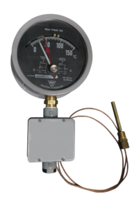
This happens because, unlike the oil top temperature monitor, which operates on the principle of direct measurement in the transformer, winding temperature measurement is performed indirectly. That is, these monitors use pre-determined parameters and the instantaneous current value to determine an average temperature rise value for the winding. Therefore, they are not able to effectively identify if the temperature change occurs in a single, isolated region of the winding; in other words, this region may be practically “invisible” to these indirect temperature rise monitors (this includes the analog indirect monitors in the photo above and even the more modern digital ones).
Returning to the main topic of this article: it is important to emphasize that altering the thermal profile will not cause immediate equipment failure, but it will certainly cause localized damage to the insulation and will reduce the projected lifespan of the asset.
In short, what happens is the following:
The magnetic design (current distribution, magnetic field, and loss profile) alters the thermal design (temperature distribution), which has a direct and fundamental influence on the electrical insulation design (loss of point insulation capacity), leading the equipment to electrical failure (total insulation breakdown and electrical discharge).

A reverse current in the transformer can cause a change in the magnetic field distribution and localized heating of the windings, thereby causing degradation of the insulation in this region, generating conditions that can lead to dielectric failure of the equipment.
The magnetic design (current distribution, magnetic field, and loss profile) alters the thermal design (temperature distribution), which has a direct and fundamental influence on the electrical insulation design (loss of point insulation capacity), leading the equipment to electrical failure (total insulation breakdown and electrical discharge).
Obviously, it’s not possible to generalize this (somewhat tragic) conclusion: not every transformer exposed to reverse flux will fail prematurely. The objective of this article is to discuss this topic to highlight some important points that interfere with this behavior and that can be evaluated to determine the severity of this condition. Some of the main ones are listed below:
- Electromagnetic operating characteristics of the transformer;
Power and voltage of the transformer; - Arrangement and constructive geometry of the windings;
- Constructive characteristics of the complete active part and tank;
- Quantity and distribution of stray magnetic flux;
- Level of winding temperature rise (hotspot factor);
- Temperature rise of the design oil;
- Loading conditions;
- Preservation of insulation.
And lastly: How to monitor this condition in transformers?
For transformers with direct temperature measurement in the windings, such as those using fiber optics, the issue is simple because it involves observing the temperature rise values of the winding or the transformer’s hardware during various operating conditions.
For transformers without direct temperature measurement, the best alternative would be to increase the frequency of dissolved gas analyses in the insulating fluid (a period of 6 months or less between each sample can be used as a reference, depending on the application and operating conditions of the transformer). In these cases, a localized heating event in the winding will cause degradation of the insulating paper and, consequently, generate mainly the key gases Carbon Monoxide (CO) and Carbon Dioxide (CO2), in addition to other gases associated with the heating of the oil as well.
Finally, it is worth noting that, based on data obtained directly or indirectly, it is possible to determine some conditions for preserving the equipment’s lifespan. For this, numerical simulation tools based on finite elements could be used, for example, to determine the distribution of losses and temperature rise in the equipment. With this information, an operating power limit could be assigned, or the natural or forced cooling system could be optimized to control the temperature and prevent accelerated aging of the transformer insulation, which could lead to premature dielectric failure. This, in addition to causing damage to the asset, can impact the reliability indices of the electrical system.