Everyone gets extremely curious when they come across extremely old transformers still in operation. It’s not uncommon to find posts on social media, especially LinkedIn, with photos of these old machines in operation.
In these posts, it’s also common to find comments from nostalgic people saying the “famous” phrase:
“These are good pieces of equipment! They don’t compare to what’s produced today…”
I agree that an old piece of equipment in operation is interesting. But I disagree with the statement that only those transformers were “better” for two main reasons:
1. Because we don’t know the conditions to which these pieces of equipment were exposed throughout their useful life. What was the operating temperature? What was the applied load? How long was it actually kept energized? All these conditions determine how much of the equipment’s useful life was consumed over time.
2. Because we don’t know the real situation of the remaining useful life of these assets… they may be nearing the end of their lifespan and fail at any moment, without there being time available for any intervention or load shifting.
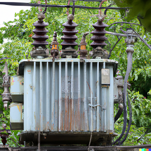
These old transformers are similar to the one in the photo at the beginning of this article (which was generated by the DALL-E artificial intelligence) and hark back to a time when projects were conceived with a different calculation methodology: the design needed to be robust enough to absorb the different characteristics of the materials available for manufacturing (parts and components with less uniformity due to less demanding quality control compared to today). It’s also important to mention that the tools available for analyzing the safety margin of projects did not have the accuracy and ease of use that we are accustomed to today (considering, for example, computational tools for numerical simulation). Therefore, among other reasons, even with greater distances and sizes, it is not possible to say that the old designs were “better”.
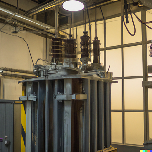
I took the opportunity to ask the DALL-E artificial intelligence to generate an image of an old transformer that powers a commercial building, and the result is the image shown to the side.
So, how do you know when a transformer is at the end of its useful life?
The most commonly used criterion for determining the aging of a transformer is the preservation of the insulation characteristics of the cellulosic material. When a decrease in the insulation capacity of this material occurs, any electrical demand, even under nominal operating conditions, can cause equipment failure due to dielectric issues.
Thus, the determination of the useful life of cellulosic insulation (measurement of insulating paper wear) is given by measuring the degree of polymerization (DP). The DP of insulating paper is generally between 1400 and 1200 when new. However, after undergoing drying processes during transformer manufacturing, which expose the active part to high temperatures, the DP decreases and tends to settle in the 1000 range. With equipment operation, the paper degrades and the DP decreases, effects caused by the intrinsic temperature increase and the presence of oxygen in the insulating paper. The limit commonly used as a criterion for the end of the useful life of insulation is approximately DP = 200.
Obviously, measuring the GP (Ground Percentage) is a very effective strategy for determining the remaining useful life of the equipment. However, this measurement requires taking a paper sample from inside the equipment. This procedure is somewhat complex, and therefore, the most current technical specifications often require that a paper sample be placed in an easily accessible location inside the transformer, near an inspection window, for example.
However, regardless of where the insulating paper sample is collected for GP measurement testing, whether from the active part or the sacrificial sample, the necessary intervention on the transformer is quite complex. This complexity is related to the process steps, the main ones being: de-energizing the equipment, reducing the insulating fluid level, accessing the internal point, collecting the sample, and restoring the insulating fluid. These steps often make GP verification unfeasible while the transformer is in operation because they must be performed by a specialized team with appropriate equipment to avoid introducing non-conformities into the equipment under analysis, such as the entry of moisture or particulates into the insulating oil and active part during the sample collection process.
But ultimately, what can be done to monitor the lifespan of a transformer?
Considering the real-world reality of transformer operation, a world that imposes penalties for power outages and where any equipment shutdown must be planned in advance and even avoided, monitoring actions for operating conditions can and should be adjusted to minimize intervention in the equipment.
In this case, the most common tests that can be performed with the transformer in operation are listed below:
- Gas chromatographic and physicochemical analysis of insulating oil: this test will determine the concentrations of dissolved gases in the insulating oil. This point could warrant an entire article, but, in short, it can be assumed that any incipient defect in the active part of a transformer, including those that may arise with operating time and aging of the insulating paper, begins to show signs in the dissolved gases and physicochemical characteristics of the insulating oil. Collecting the insulating oil sample for this test is relatively simple and can be done with the equipment energized, meaning it requires minimal intervention in the transformer’s operation.
- Partial Discharge Measurement and Detection: When a transformer is on the verge of insulation failure and the paper is worn out, it will exhibit some level of partial discharge. The measurement of the partial discharge level can be performed directly or indirectly. Direct measurement is performed by injecting a voltage level into the equipment and measuring the partial discharge level. This method is quite accurate; however, it requires the transformer to be de-energized for measurement. To perform the partial discharge measurement indirectly, which is also quite accurate, the acoustic emission method can be used. This method is based on the installation of sensors (microphones) in the equipment that detect the level of partial discharges through the acoustic emission generated by them. A major advantage of this method is that it is possible to use signal triangulation and, through 3D signal processing techniques, it is possible to identify the region of the equipment that is generating the highest discharge level. This location, even if approximate, can greatly assist in developing an intervention strategy, directing efforts directly to the causative element, which could be a winding of a particular phase, a connecting cable, a switch, or a bushing.
- Insulation power factor: when monitoring the preservation of equipment insulation, the tangent delta and insulation power factor of the windings and bushings can be measured. This test, although it must be performed with the transformer de-energized, is relatively simple and can indicate a level of wear on the insulation of the transformer elements. This test has limited capacity to determine when the equipment should be taken out of operation, but it can be used based on a reference (obtained with a new transformer, for example) and generate a trend analysis over the operating time, informing intervention and maintenance strategies.
- Frequency Response Analysis (FRA): Transformers are naturally exposed to typical operating events, and each occurrence generates changes in their active part and, consequently, in their operating characteristics. In this sense, to identify, for example, if the equipment has suffered a serious incident that significantly altered the composition of the active part, it is possible to use the Frequency Response Measurement (FRA) test of the windings. This test generates a kind of signature of the equipment, based on its constructive characteristics. Thus, throughout its useful life, this test can be performed to verify if the constructive characteristics are preserved. Therefore, this test is widely used for evaluation after large-magnitude events, such as short circuits, internal inspections, bushing and commutator replacements, and/or logistical movements of the equipment between operating locations.
- Thermography: Thermographic recording is also a non-invasive technique that allows temperature measurement without direct contact with the object being analyzed. This technique is widely used in transformers to detect potential thermal problems, such as faulty bushing connections, hot spots in surge arresters, blocked cooling systems, and circulating currents that can lead to localized overheating in the tank walls which, when in contact with oil, can generate gases. Thermography is an important technique for preventive maintenance and fault diagnosis in equipment throughout its useful life.
It is worth noting that there are several articles, standards, and CIGRE guides with a wealth of information on the subject of monitoring the operating conditions and service life of a transformer. The objective of this article was to present some approaches to older transformers in operation and the main tests that can be performed on this equipment. It is very important that each particular situation be analyzed so that appropriate actions can be taken to preserve the asset’s service life or to minimize the costs involved in maintenance or post-failure repair interventions, for example.
Don't worry, if you're unsure which strategy to use, we're here to help!
If you are unsure about the interpretation of the results of dissolved gas and physicochemical tests of the insulating oil, have not reached a conclusion on whether to apply the direct (electrical) or indirect (acoustic) partial discharge measurement method, or whether the FRA response is adequate, or even where the heating points evidenced in the thermography originate, you can count on the TRINSE Technical Team, who will certainly analyze your situation and provide you with technical arguments to make the most correct decision possible, always seeking to increase the useful life of the equipment and, when this is no longer possible, identify the most appropriate time for intervention and/or minimize the costs of a recovery.