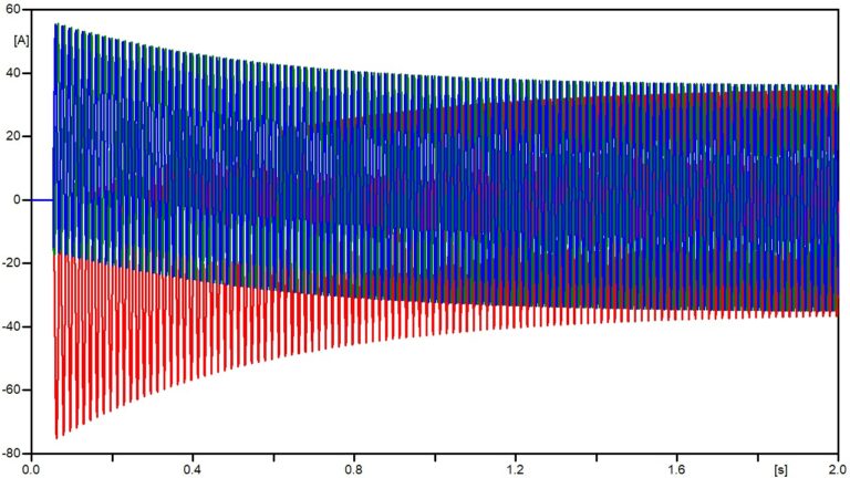
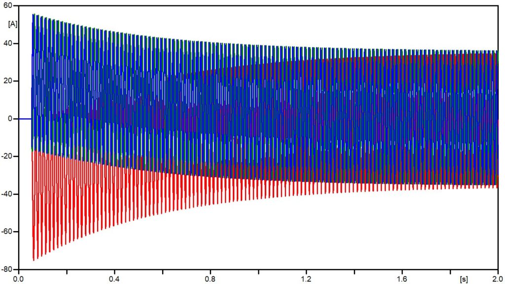
The initial magnetizing current (inrush) that occurs in transformers also occurs during the energization of shunt reactors with iron cores and air gaps. The inrush phenomenon, which can be defined as an energizing overcurrent, is characterized as a sinusoidal current added to a DC component with exponential decay. This decay depends on the X/R ratio, which in turn depends on the intrinsic constructive characteristics of the equipment.
Here we can already highlight the first major difference between the magnetization behavior of shunt reactors and transformers: the current damping time.
This occurs because the X/R ratio in shunt reactors commonly presents higher values, given the reactance and characteristic resistance of these devices. It is important to note that the damping time depends on the magnetic characteristics of each design and the system where the equipment is installed, and cannot be generalized.
However, generally, for shunt reactors, the damping time of the magnetization phenomenon can be up to a few seconds, while for transformers, it is commonly only a few milliseconds (a few network cycles).
Regarding the continuous current component in the shunt reactor, its prolonged duration can negatively impact the saturation of the system’s current transformers (CTs) and can also damage the reactor’s insulation and connections due to overheating. It is important to note that when the CT is saturated, its secondary measurement becomes distorted, resulting in inaccurate protection for substation equipment and even leading to inappropriate actions and unscheduled shutdowns.
Now, regarding the amplitude of the magnetizing current, this value can typically reach 2 to 5 times the nominal current, according to some typical modeled cases.
Typically, the amplitude of the magnetizing current in shunt reactors is not as high as that of transformers.
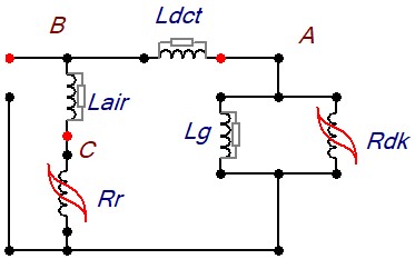
The amplitude of the magnetizing current, as well as the damping time, depends on the magnetic characteristics of each design and the system where it is installed, as well as the instant of energization and the harmonic content during energization. All these variables are calculated; however, most models represent the reactor as a circuit with a resistor (R) in series with an inductor (L). This modeling does not represent the fundamental non-linearity characteristic of the ferromagnetic core of the equipment, which exhibits saturation levels during the energization event.
Therefore, to correctly model the low-frequency nonlinear magnetization electromagnetic behavior of shunt reactors in the electrical system, computer programs are used that employ circuit models built with parameters based on the magnetic characteristics of each specific design. The most significant aspects in defining these parameters are linked to the constructive characteristics of the reactor’s active part, including the core, air gaps, and windings.
Therefore, with this information, the equivalent electrical circuit is constructed, derived from the transformation based on the electrical and magnetic duality of the circuit. With this equivalent model of the shunt reactor, built with non-linear elements, it is possible to simulate its electromagnetic performance with much greater precision in specific electrical system analysis software, including ATP and others.
Therefore, considering the growing demand for adequate modeling of electrical systems, it can be highlighted that these low-frequency studies performed with models that consider the non-linear electromagnetic characteristic become fundamental for the analysis of reactor performance in the electrical system, especially in relation to typical operational challenges such as inrush currents, undervoltages, overvoltages, and ferroresonance.