High-power transformers (greater than several hundred MVA) require careful analysis regarding losses in metallic parts. The design demands specific precautions to enable effective control of the intense magnetic fields derived from the load current in order to avoid the emergence of concentrated hot spots on any magnetic metallic barrier, including the walls of the equipment tank.
In this sense, the purpose of using shielding in the tank is to control losses due to the stray magnetic field of the windings that reach this region. Silicon steel is commonly used for shunt-type shielding, which has excellent magnetic permeability, attracting the stray magnetic field and offering an alternative low-reluctance path, protecting the tank from the generated parasitic losses.
However, when the transformer’s design requires the shielding to have mechanical flexibility to conform to the side of the tank, a shield-type shield made of a good electrical conductor, such as aluminum or copper, can be used.
The operation of aluminum shielding differs from that of shunt shielding. In this case, when the stray magnetic field reaches the shield, eddy currents are induced in the shield, and the magnetic field generated by these currents repels the magnetic field that generated them, protecting the area of the tank where the shield is installed. The induced current in the shield should also be evaluated, but normally, eddy losses do not have the potential to damage the equipment. Another important detail is that shield-type protections made of electrically conductive material repel the stray magnetic field to another point in the transformer, often potentially shifting the heating problem to another area such as the bottom, cover, and mounting hardware of the active part.
Study Case
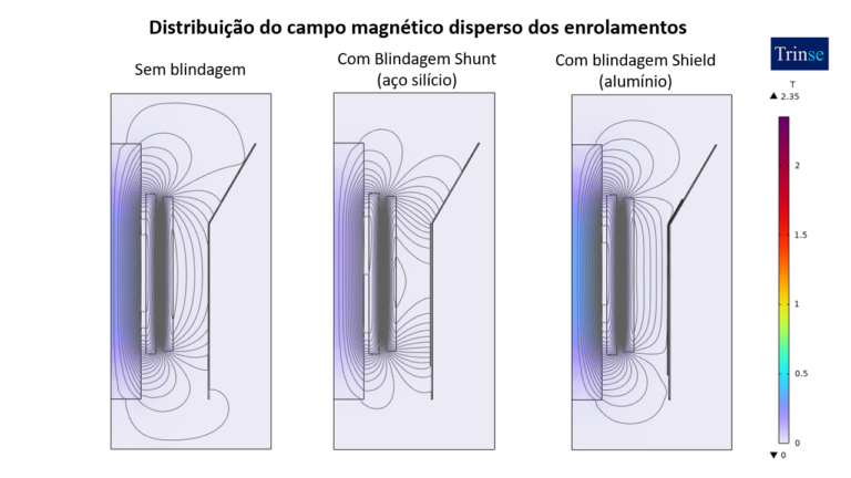
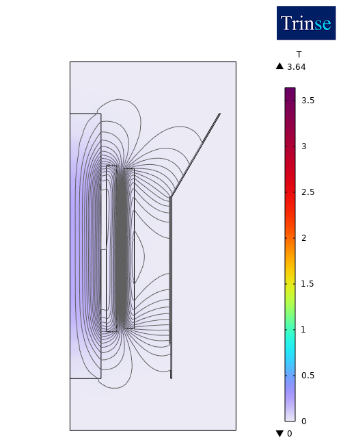
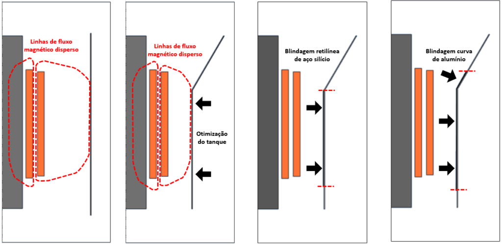
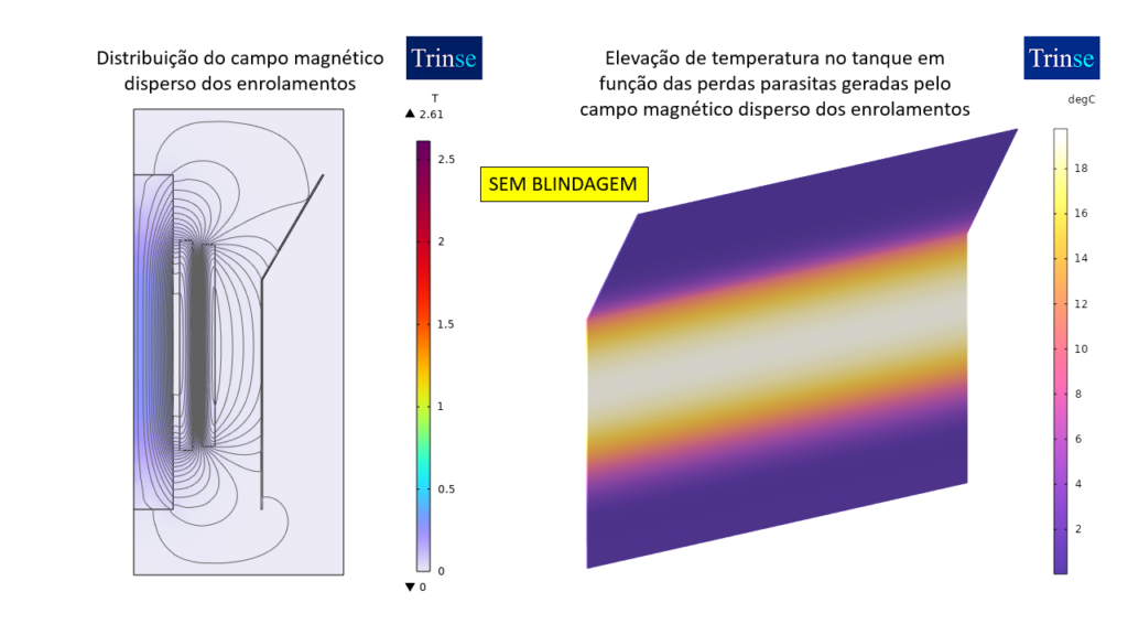
A case was simulated showing the heating behavior of the tank as a function of the stray magnetic field of the windings of a given transformer. The first study was carried out with the tank optimized in curvature to reduce the use of insulating oil and without the use of magnetic shielding, as shown in the following figure.
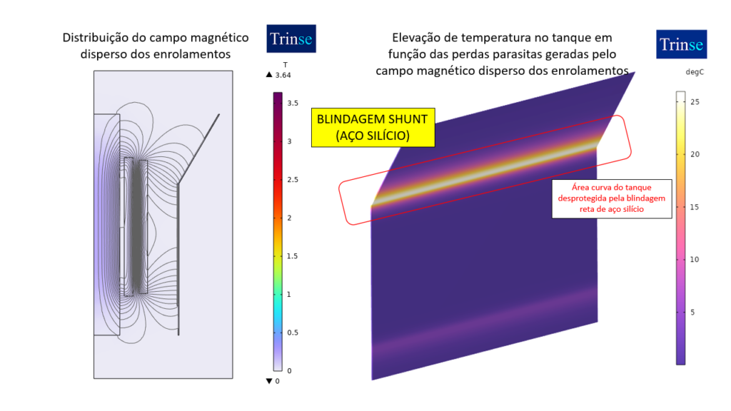
To overcome this overheating, the first option used was a silicon steel shunt shielding pattern. This shielding concept is installed only on the flat walls of the tank, and the resulting temperature increase can be seen in the following images.
What can be observed is that, since the shielding only protects the flat part of the tank, a region at the top is exposed to the effects of the stray magnetic field, and the resulting temperature increase in this region is even more critical. This phenomenon occurs because the magnetic field concentrates at its upper end and reaches the tank before returning to the windings.
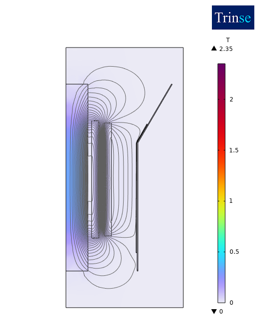
To overcome this difficulty, armor conforming to the tank’s geometry can be used, in this case using electrically conductive material, such as aluminum. The results of this same configuration using shield-type armor can be seen in the following figure.
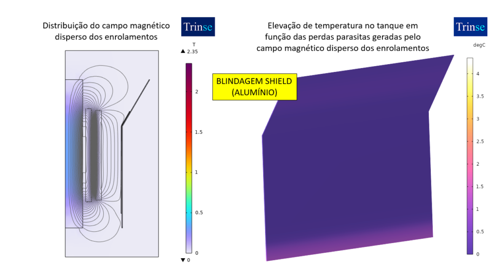
Conclusion: The temperature rise values, which were close to 20°C on the unshielded tank wall, became even worse when silicon steel shunt shielding was used (the rise values reached 25°C). To overcome this situation, shield-type armoring made of electrically conductive material (aluminum) was used, protecting even the curved part of the tank’s geometry.
These heating points have the potential to form gases that dissolve in the insulating oil and can also cause rapid degradation of the paint and gaskets used to seal the insulating fluid in the equipment. This problem, which can be further aggravated during eventual emergency overloads, is solved with the use of properly designed shielding.